
Opening up the packet you will be greeted with these parts, the board, extended gpio header, 16 pin socket for the lcd to plug into and potentiometer for adjusting the screen.
firstly we want to start with the gpio, with a bit of blue tack or putty secure the board in place the will ensure you get a perfect right angle connection and not become skew whiff.


Next is the potentiometer, keep the flat side to the left as per picture so the two pins on the flat side go in the two holes and the single pin under the curved area on the right will go in the hole on the right as per picture.

Now it's time to add the 16 way header, this is so you can swap and change between lcd boards, if you really don't want to swap you could solder the LCD board straight to it, but for this tutorial I will treat the board as I originally designed it for. However if you go straight to the bottom I have added how to do this and make it more permanent.

Again the putty is a great way to hold it all in place whilst soldering the pins.
Now, providing you have soldered the pins to the LCD board and plugged it in we are ready to move on to the software side of things.


Following Jason's great blog post http://www.boeeerb.co.uk/pi-lcd/ don't forget to reboot at the end with:
Sudo shutdown -r now
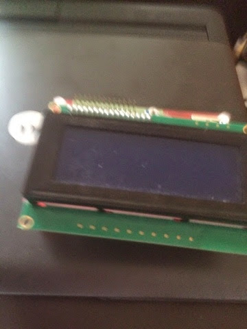
When you restart you should be greeted with something like this.


At the bottom of the blog on boeeerb there are a couple of demo scripts, here is a picture to show it working.

The whole thing from start to finish should take you around 1-2 hours depending on how much updates your device needs, solder skills and typing speed.
More can be found on eBay and various raspberry pi online shops.
Making the board support more permanent:
If you decide on a more permanent solution, don't solder the black 16 pin to the board, solder the male 16 pin header so the shortest end goes into the MyPiFi board then place the LCD over the longer pins and solder, you need to do it this way round or the pins could touch the pi. You could once soldered cut the pins down to make them flush.


Thank you to averagemanvspi who has listed the pins as: LCD_RS = 7, LCD_E = 8, LCD_D4 = 25, LCD_D5 = 24, LCD_D6 = 23, LCD_D7 = 18 (BCM numbering)

Also thank you to @boeeerb for his write up for lcdproc and the fritzing picture.
PenguinTutor has written about his experience with his here. http://www.penguintutor.com/news/raspberrypi/pibow-lcd
LCD Schemetics:

Here are some of the tweets I've recieved from users:


Penguintutor has also done a brilliant guide to get started here: http://www.penguintutor.com/programming/raspi-lcd
No comments:
Post a Comment
Please feel free to comment would love to hear your ideas.